
2026 Defender: How Does the Electrical System Work?
The Defender uses a sophisticated 12-volt electrical architecture that powers vehicle systems and coordinates communication among dozens of electronic control modules. Depending on the selected powertrain in the Canadian market, the electrical system may also incorporate mild-hybrid or plug-in-hybrid technologies that work alongside the conventional 12-volt network. Regardless of configuration, the Defender continuously manages battery charging, electrical loads, diagnostics, and communication through multiple electronic networks to support on-road driving, off-road capability, driver assistance technologies, and vehicle comfort systems.
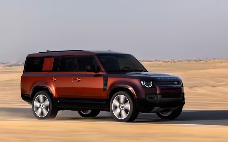
The electrical system combines a 12-volt battery, intelligent battery monitoring, an alternator or a DC-DC converter, depending on the powertrain, multiple fuse panels, protected wiring harnesses, electronic sensors, and distributed control modules connected via Controller Area Network (CAN) communication. These components continuously exchange information to ensure reliable operation under a wide range of Canadian driving conditions, including low temperatures, towing, and off-road use.
2026 Defender Core Components
12-Volt Electrical Architecture
The foundation of the Defender electrical system is its 12-volt network.
This architecture powers systems including:
exterior lighting
interior lighting
infotainment
climate control
windshield wipers
power windows
electronic steering systems
driver assistance technologies
electronic locking systems
body electronics
Although certain Defender powertrains include higher-voltage components for hybrid operation, the conventional 12-volt system remains essential because it initializes vehicle electronics before the engine or hybrid systems become fully operational.
Battery Management
Battery management is performed electronically through an intelligent battery monitoring system.
The system continuously evaluates:
battery voltage
charging current
battery temperature
state of charge
electrical demand
Using this information, the vehicle adjusts charging strategy according to operating conditions.
Examples include:
cold starts
highway driving
heavy accessory use
towing
off-road operation
The battery management system also prioritizes electrical loads when battery voltage decreases, helping preserve sufficient power for essential vehicle functions.
Alternator or DC-DC Converter
The method used to maintain battery charge depends on the Defender powertrain.
Conventional Powertrains
Gasoline and diesel engines typically use an engine-driven alternator.
The alternator converts mechanical energy from the engine into electrical energy to:
recharge the battery
supply electrical accessories
maintain stable system voltage
Charging output varies continuously according to battery condition and electrical demand.
Electrified Powertrains
Defender models equipped with mild-hybrid or plug-in-hybrid systems incorporate additional power electronics.
These vehicles use a DC-DC converter to transfer energy from the high-voltage battery to power the 12-volt electrical system.
This arrangement allows conventional electrical accessories to operate normally while integrating with the hybrid propulsion system.
Electronic Control Modules
The Defender contains numerous electronic control modules distributed throughout the vehicle.
Examples include:
Powertrain Control Module
Body Control Module
Transmission Control Module
Suspension Control Module
Terrain Response® Control Module
Infotainment Control Module
Climate Control Module
Airbag Control Module
Each module performs specialized functions while communicating continuously with the rest of the vehicle.
Rather than operating independently, these modules share sensor information and operating commands across the electrical network.
CAN Bus Communication
The Defender relies extensively on Controller Area Network (CAN) communication.
Instead of wiring each signal individually, CAN networks allow electronic modules to exchange information over shared communication circuits.
Examples of shared information include:
wheel speed
steering angle
engine speed
suspension position
battery condition
terrain selection
braking information
This communication architecture reduces wiring complexity while allowing rapid coordination between multiple systems.
The result is improved integration of technologies such as Terrain Response®, adaptive suspension, electronic stability control, and driver assistance features.
Fuse Panels
Electrical circuit protection is provided through multiple fuse panels positioned throughout the vehicle.
These fuse panels protect circuits serving systems such as:
lighting
infotainment
HVAC
trailer wiring where equipped
power outlets
seat functions
driver assistance technologies
Each fuse is calibrated for the expected electrical load of its assigned circuit.
If an abnormal current condition occurs, the fuse interrupts the circuit before wiring or electronic components can be damaged.
The Defender uses multiple fuse locations due to its extensive electrical architecture and distributed electronic systems.
Sensors
The electrical system relies on hundreds of sensor inputs to monitor vehicle operation.
Examples include:
battery sensors
wheel speed sensors
ride height sensors
steering angle sensors
temperature sensors
pressure sensors
rain sensors
ambient light sensors
camera systems
radar sensors
Sensor information enables the control modules to make continuous operating adjustments in response to changing driving conditions.
Many safety and convenience systems depend on accurate sensor communication.
Wiring Protection
The Defender wiring harnesses are designed to withstand demanding operating environments.
Protection measures include:
abrasion-resistant coverings
waterproof connectors
sealed electrical terminals
protective routing
flexible conduit
corrosion-resistant materials
These features are particularly important because the Defender is engineered for off-road operation involving water, mud, vibration, and changing temperatures.
Proper wiring protection helps maintain long-term electrical reliability under these conditions.
Diagnostics Guide
Diagnostic Trouble Codes
Every major electronic system in the Defender continuously performs self-diagnostic checks.
If abnormal operating conditions are detected, the appropriate control module stores a Diagnostic Trouble Code (DTC).
These codes help identify issues involving:
sensors
communication networks
charging systems
electrical circuits
emissions systems
hybrid systems where applicable
suspension electronics
Diagnostic equipment can retrieve stored DTCs for further analysis.
Many electrical concerns can be identified before noticeable operating symptoms develop.
Common Electrical Warning Symptoms
Electrical faults may generate several different warning indicators depending on the affected system.
Possible symptoms include:
battery charging warnings
electrical system fault messages
infotainment interruptions
intermittent lighting operation
driver assistance warnings
terrain response messages
suspension notifications
reduced accessory operation
Some warnings involve only a single electronic module, while others may affect several interconnected systems because of the shared communication network.
Communication Faults
Because numerous electronic modules exchange information continuously, communication interruptions may generate multiple warning messages simultaneously.
Potential causes include:
damaged wiring
connector corrosion
voltage instability
module faults
communication network interruptions
The vehicle's diagnostic system records communication-related DTCs that assist technicians during troubleshooting.
Cold-Weather Performance
Canadian winters place additional demands on the Defender electrical system.
Low temperatures reduce battery efficiency while increasing electrical demand from systems such as:
heated seats
heated steering wheel
windshield defrost
heated windshield where equipped
heated mirrors
cabin blower
exterior lighting
The battery management system continuously adjusts charging strategy to compensate for these increased demands.
Hybrid-equipped models also coordinate high-voltage and 12-volt electrical operation during cold-weather driving.
Maintenance Guide
Routine electrical system maintenance helps preserve reliable operation throughout the service life of the Defender.
Recommended inspections include:
battery condition testing
charging system evaluation
alternator or DC-DC converter inspection
battery terminal inspection
fuse inspection
wiring harness inspection
connector corrosion inspection
software updates where applicable
diagnostic system scanning
Vehicles frequently operated in Canadian winter conditions also benefit from periodic inspection for road salt accumulation around exposed electrical connectors and underbody wiring.
After off-road driving, inspection for mud, debris, or physical damage around wiring harnesses and connectors is also recommended.
Because many electrical systems depend on software integration, periodic software updates may improve communication, diagnostics, and control strategies.
During scheduled maintenance at Land Rover Richmond, technicians can retrieve stored diagnostic information, evaluate battery performance, inspect charging components, verify CAN network communication, and confirm proper operation of electronic modules using manufacturer-approved diagnostic equipment. Routine maintenance helps ensure reliable starting, consistent electronic operation, effective driver assistance performance, and dependable operation of the advanced electrical systems that distinguish the Defender.
2026 Defender FAQ
1. Does the 2026 Defender still use a conventional 12-volt electrical system?
Yes. Every current model uses a 12-volt electrical architecture to power vehicle electronics, even on models equipped with mild-hybrid or plug-in-hybrid powertrains.
2. How is the 12-volt battery charged?
Conventional gasoline and diesel models use an engine-driven alternator. At the same time, electrified versions also incorporate a DC-DC converter that transfers energy from the high-voltage battery to maintain the 12-volt system.
3. What is the purpose of CAN bus communication in the Defender?
The CAN bus allows electronic control modules to exchange information rapidly over shared communication circuits, improving coordination between systems such as Terrain Response®, suspension, braking, and driver assistance technologies.
4. Why can one electrical fault trigger several warning messages?
Many vehicle systems communicate through shared electronic networks. A communication interruption or voltage-related issue may affect multiple control modules, causing several warning messages to appear simultaneously.
5. What maintenance is recommended for the Defender electrical system?
Routine maintenance includes battery testing, charging system inspection, software updates, wiring and connector inspection, fuse evaluation, and electronic diagnostic scanning. Land Rover Richmond can perform these inspections using manufacturer-approved diagnostic equipment.
*Disclaimer: Content contained in this post is for informational purposes only and may include features and options from US or internacional models. Please contact the dealership for more information or to confirm vehicle, feature availability.*


